GNSS antennas
A GNSS antenna must receive the right‑hand circularly polarised signals from the satellites while rejecting left‑hand signals reflected from the ground. These examples range from a simulated circular patch to simple and stacked ceramic patches and a short quadrifilar helix.
A circular patch on a small groundplane
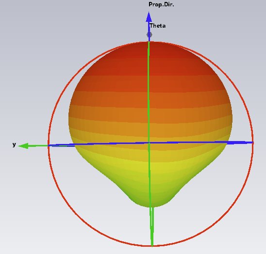
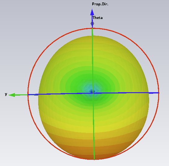
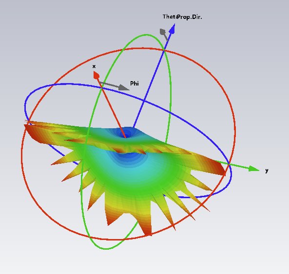
A circular patch on a small square groundplane, fed at two points in phase quadrature. Right‑hand circular polarisation (RHCP) is radiated along +z. Left‑hand circular polarisation (LHCP) is radiated backwards, at a level set by the size of the groundplane.
The axial ratio is low in both the +z (RHCP) and −z (LHCP) directions, but becomes much larger near the plane of the patch, where the polarisation is close to linear. In a GNSS application the rear radiation receives the LHCP ground‑reflected signal, prejudicing the accuracy of the position fix.
Simple ceramic patches
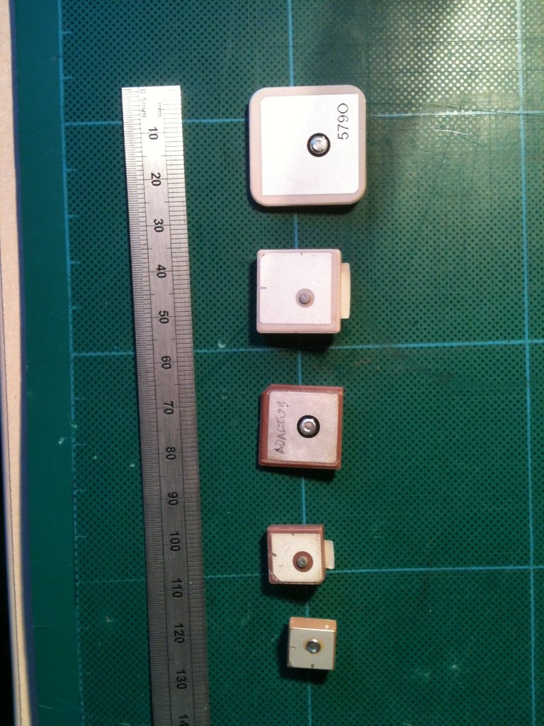
A collection of simple ceramic patches for GPS. Only the larger ones (18 and 24 mm square) have enough bandwidth to cover the upper L band (about 1559–1610 MHz, carrying GPS L1, Galileo E1, BeiDou B1 and GLONASS G1) for all constellations.
The single‑fed, cropped‑corner design severely limits the axial‑ratio bandwidth.
A stacked ceramic patch
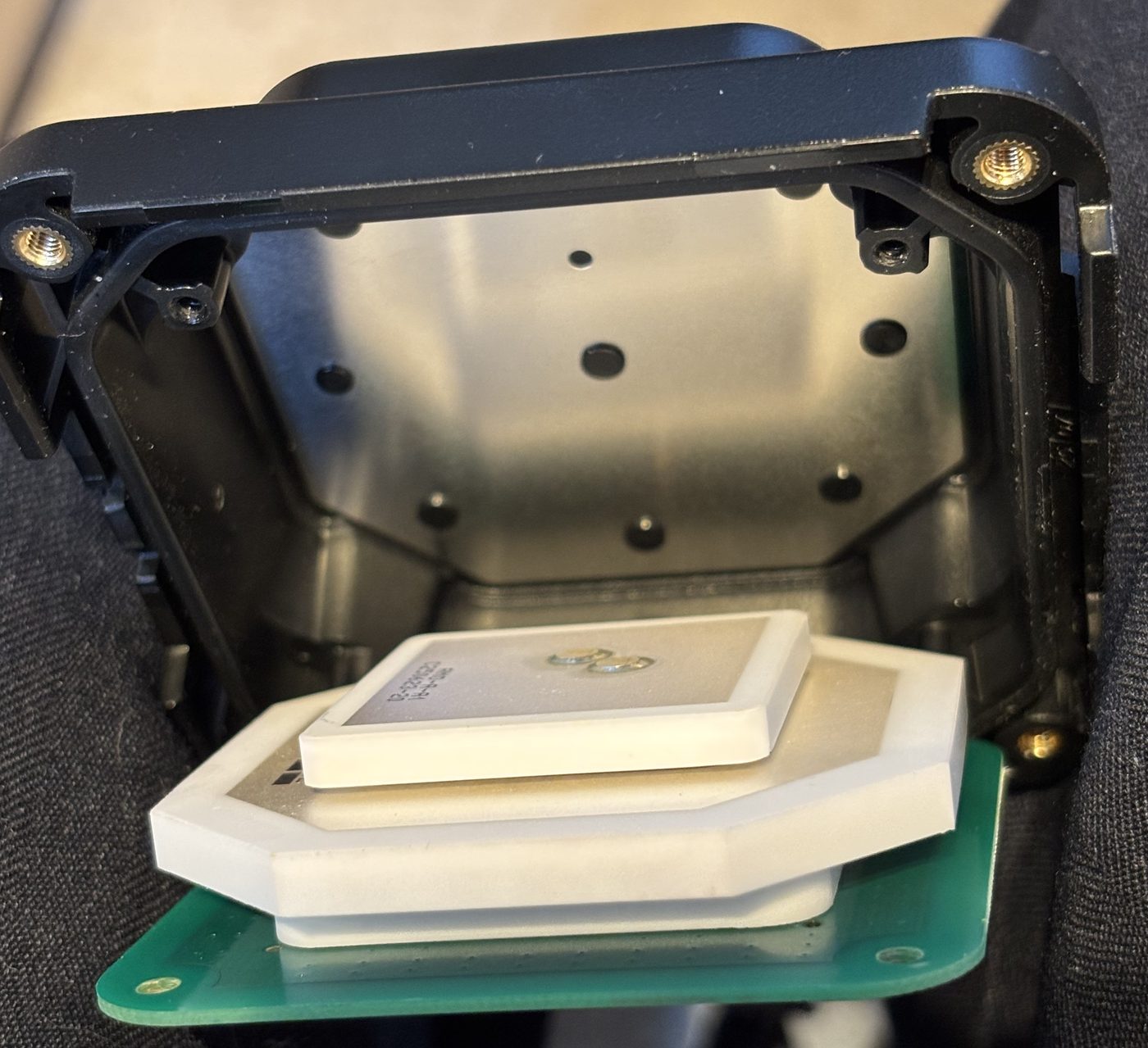
A stacked ceramic patch antenna providing operation on all current GNSS frequency bands. It is built from three stacked ceramic tiles with an aluminium parasitic patch (the shiny top surface).
Like most patches of this kind, it needs to be mounted on an external groundplane.
A short quadrifilar helix
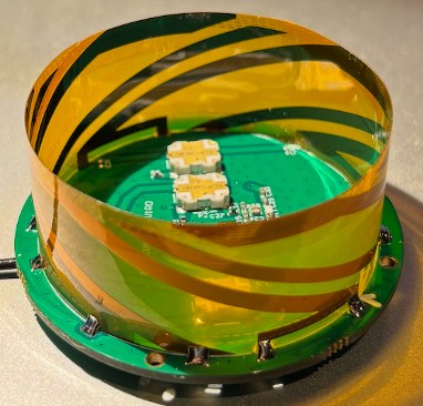
A typical short quadrifilar helix antenna with four feed points, driven through 90° hybrids and a 180° phase‑shift line or 180° balun.
Antennas of this type usually include an LNA, which provides a low system noise figure even after allowing for the loss of the connecting cable.
Need a GNSS antenna that works on your product?
Antenna choice, groundplane and placement all affect position accuracy. A short conversation is the best way to start.